10+ er diagram symbols
An entity is a thing person or. In order to create one you will need a tool that has the building blocks for ER diagram.

The Sacred Womb Sacred Geometry Symbols Fibonacci Sacred Geometry
Let us see one by one below.
. ER Diagrams are most often used to design or debug relational databases in the fields of software engineering business information systems education and research. Rectangles are used to represent the entity in the diagram. Fluid Power Symbols 210 An arrow parallel to the short side of a symbol within the symbol indicates that the component is.
UML Diagram What is a UML Diagram. You can add images infographics clipart special symbols icons and more. Rose hkrisroseens-lyonfri Version 37 February 16 1999 Abstract XY-pic is a package for typesetting graphs and diagrams.
Lets create an ER diagram for a data model using Vertabelo. 6 Best ER Diagram Tools in the Market 1. Creating ER Diagram via GitMind.
4121 Below Fluid Level 4122 Above Fluid Level The return line is drawn to terminate at the upright legs of. The software is able to create ERDs for relational and NoSQL databases. The Basic version.
Using graphical tools to assist in their design becomes essential. XY-pic Users Guide Kristoer H. The client must purchase one or more menu items while each menu item is served by one attendant.
DbSchema is a database design and management system that is based on an ER diagram tool. Best VPNs of 2022. Several such symbols may be used in one diagram to represent the same reservoir.
Creating ER Diagram via Microsoft Word. In this component diagram tutorial we will look at what a component diagram is component diagram symbols and how to draw one. There are over 34000 different symbols to.
That being said we listed the most accessible tools to create ER diagram. What is Component Diagram. Name of the Entity is.
You can use a component diagram example below to get a quick start. Which one is an ER diagram. Weve also added some templates for you to get started quickly.
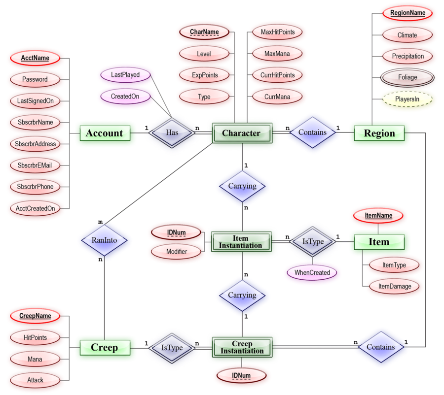
How to Draw an ER Diagram. This ER diagram tutorial will cover their usage history symbols notations and how to use our ER diagram software to draw them. The Chen notation does not show explicitly the FK relations as the accepted answer already explains while other notations can do this.
The notation has evolved from the work of Grady Booch James Rumbaugh Ivar Jacobson and the Rational Software Corporation to be used for object-oriented design but it has since been extended to cover a wider variety of software engineering projects. Consider a simple scenario in which a client orders food at a restaurant. One answer here even states that the Chen notation is the ERD while Crow Foot notation is said to be an EAD Entity Attribute Diagram see JoshuaGuttman.
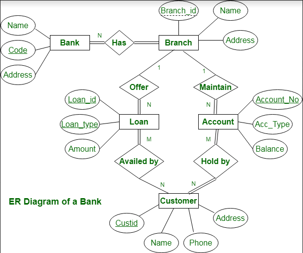
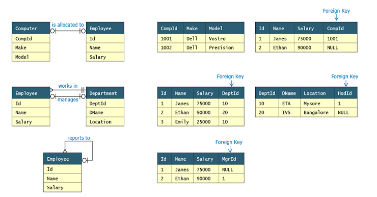
Lucidchart This software is one of the popular online ER diagram tools which allows you to create not only basic ER diagrams with in-built templates but provides more useful functionalities. The ER Diagram show the relationship between entities tables and the primary key-foreign key relationships between the tables relationships. The Starter version is free and supports two database models with 10 tables per model.
Weve also added some templates for you to get started quickly. An Entity Relationship ER Diagram is a type of flowchart that illustrates how entities such as people objects or concepts relate to each other within a system. 5 Methods on How to Make ER Diagram.
Entity-relationship modeling or ER Diagram symbols are part of a conceptual approach to design that models objects as abstract data types and the relations between these objects as predicates. Since ER diagram is the pictorial representation of real world objects it involves various symbols and notation to draw the diagrams. Component diagrams are used to visualize the organization of system components and the dependency relationships between.
Well show you the best database diagram tools to give you the edge. First identify the entities in your database. The diagram editor provides a library of ERD symbols and the designer places them on the canvas to create an entity and add attributes to it.
UML is a way of visualizing a software program using a collection of diagrams. To cut the chase here are the recommended tools for ER diagram creation.

Introduction To Er Diagram Model Knoldus Blogs
Er Diagram Of Bank Management System Geeksforgeeks

Imindmap Gallery Imindmap Mind Map Mind Map Art Map

Relative Clauses Relative Clauses Mind Map Grammar

Introduction To Er Diagram Model Knoldus Blogs

What Is An Er Diagram And How To Implement It Edureka
What Is An Er Diagram And How To Implement It Edureka

Introduction To Er Diagram Model Knoldus Blogs
What Is An Er Diagram And How To Implement It Edureka
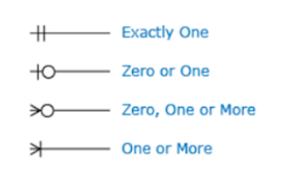
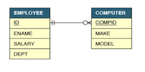
How Do We Read Cardinality In A Uml Diagram Or In E A Diagram Quora

Introduction To Er Diagram Model Knoldus Blogs
What Is An Er Diagram And How To Implement It Edureka
Entity Relationship Model Wikiwand

Pin On Report Template
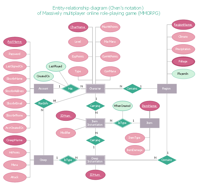
Chen S Erd Of Mmorpg Android Gui Examples Of Flowcharts Org Charts And More Erd For Online Multi Player Game

Circuit Diagram Of A Torch Circuit Diagram Diagram Electrical Diagram
What Is An Er Diagram And How To Implement It Edureka